0 How To Verify Ground Connections and Fence Ground Installation


In Article " How to Verify Ground Rod and Grid Installation ", I explained the following points:

  • Practice#2: How to Verify Ground Grid Installation,
  • Practice#3: How to Verify Ground Rod Installation.


Today, I will explain the following:


  • Practice#4: How to Verify Connection / Interconnection Installation Ground Connection Requirements and 
  • Practice#5: How to Verify Fence Ground Installation.


You can review the following Articles For more information:


Practice#4: How To Verify Connection / Interconnection Installation Ground Connection Requirements


Use the following information in this work aid and figures in the Information Section to help in identifying connections to ground as follows:

1- Determine that buried connections are made by thermite welds, brazed or approved compression connectors and the grid interconnections are approved compression type or thermite welded.

2- Verify that no mechanical connections made are buried below grade.

3- Verify that grounding conductors from one equipment unit to another have not been looped.

4- Verify that all grounding conductors are as continuous as possible and that no unnecessary connections have been made.

5- Verify if ready disconnections for test purposes are provided in grounding connections to, generator neutrals, transformer neutrals, grounding electrodes such as groundwells or groups of ground rods, switchgear equipment ground buses, and switchgear neutral buses.

6- Verify that all grounding devices and conductors are installed so that they will be protected as much as possible against mechanical injury. In frequented areas, buried conductors, 120 mm2 (No. 4/0 AWG) or less, emerging from the ground should be protected by a non-metallic conduit for 6 to 12 inches (150 mm to 300 mm) above and below grade. Conductors should be ducted below concrete or where similarly inaccessible, preferably using non-metallic pipe. Metallic conduit and cable tray  shall be grounded at each end . Make sure that these systems are electrically continuous.

7- Verify that the grounding bus forms a closed loop so that equipment ground and system neutrals tee-connected to it have 2 current paths.

8- Verify that where a site includes ground buses and ground grids in combination, and their ground resistance area overlaps, they must be interconnected by at least two conductors per bus or grid.


Exercise for Verifying Connection / Interconnection Installation Ground Connection Requirements


Question#1: Buried connections are made by three different means. What are they?
Answer: Thermite welding, brazing, and compression.

Question#2: Mechanical connections are (choose one) 1- permitted, 2- not permitted to be buried below grade.
Answer: Mechanical connections are not permitted to be buried below grade.

Question#3: Looping of grounding conductors from one equipment to another is (choose one) 1- permitted, 2- not permitted.
Answer: Looping of grounding conductors from one equipment to another is not permitted.

Question#4: All grounding conductors should be as …………..  as possible and no unnecessary connections should be made.
Answer: All grounding conductors should be as continuous as possible and no unnecessary connections should be made.

Question#5: Ready disconnections for test purposes should be provided in grounding connections to what?
Answer: to Rods, ground wells, generator and transformer neutrals, switchgear equipment and switch gear neutral.

Question#6: All grounding devices and conductors should be installed so that they will be protected as far as possible against ………………. In frequented areas, buried conductors, sized ………………… or less, emerging from the ground should be protected by a non-metallic conduit for …..  To ……..  inches above and below grade.
Answer: All grounding devices and conductors should be installed so that they will be protected as far as possible against mechanical damage. In frequented areas, buried conductors, sized 4/0 AWG (120 mm2) or less, emerging from the ground should be protected by a non-metallic conduit for 6 to 12 inches above and below grade.

Question#7: The grounding bus forms a closed loop so that equipment ground and system neutrals tee-connected to it have how many current paths?
Answer: 2 Paths

Question#8: Overlapping ground buses and ground grid areas should have a minimum how many conductors per bus or grid interconnect?
Answer: 2 Conductors


Practice#5: How to Verify Fence Ground Installation


Use the following information in this work aid to help in identifying fence grounds as follows:

1- Verify that the following fences are grounded:
  • Fences that enclose or cross over a ground grid,
  • Fences that pass under a transmission line operating at 230 kV and above.


2- Determine whether the fence has been built to an SSD/1 type. If so, no grounding is required.

3- Verify that ground wells are located as shown on the drawing used for inspection and are connected to the grounding conductor.

4- Verify that the grounding conductor has a minimum of two connections to the ground grid.

5- Verify that the peripheral grounding conductor of the substation is
approximately 3ft (1 m) outside and parallel to the fence.

6- Verify that the fence is bonded to the peripheral grounding conductor at intervals of 50 feet (15 m) with a minimum size of 70 mm2 (2/0 AWG)

7- Verify that metal posts are used for the substation fence.

8- Verify that corner and gate posts are bonded to the parallel conductor and gates are bonded to gate posts with flexible connectors.


Exercise for Verifying Fence Ground Installation


Question#1: Determine if the following fences are to be grounded:
  • Fences that enclose or cross over a ground grid.
  • Fences that pass under a transmission line operating at 230 kV and above.

Answer:
  • Yes.
  • Yes.


Question#2: A fence has been built SSD/1 type. What type of grounding is required?
Answer: none.

Question#3: Ground wells are usually located where?
Answer: diagonally.

Question#4: How many connections should the grounding conductor located outside the fence area have to the ground grid?
Answer: 2 connections.

Question#5: How far should the peripheral grounding conductor be located from a substation fence?
Answer: 2 to 3 feet.

Question#6: A substation rated above 13.8 kV has a fence bonded to the peripheral grounding conductor at intervals of …………….. With a minimum size of …………   conductors.
Answer: A substation rated above 13.8 kV has a fence bonded to the peripheral grounding conductor at intervals of 50 FEET   with a minimum size of _2/0    conductors.

Question#7: What type of posts are used for a substation fence?
Answer: metal Post.

Question#8: To what are the corner and gate posts grounded to? How are gates bonded?
Answer: Corner and gate posts must be connected to the grounding conductor. Gates must be bonded to gate posts with Parallel conductor and flexible connectors.


0 How to Verify Ground Grid and Rod Installation


In Article " How to Calculate Ground Resistance ", I explained the following points:

  • How to Measure Ground Resistance,
  • How to Estimate Minimum Ground Grid Resistance,
  • How to Estimate Upper Limit of Ground Resistance.


Today, I will explain Practice#2: How to Determine Ground Resistance and Practice#3: How To Verify Ground Rod Installation as follows.


You can review the following Articles For more information:


Follow the steps in this work aid to determine if the materials and connections used for the ground grid are correct as follows:

  • Verify that the grid wires are a minimum of 70 mm2 (2/0) bare copper wire.
  • Verify that the conductors are stranded for 35 mm2 (2 AWG) wire or larger.
  • Verify that the wires are tinned when the soil resistance is less than  70 Ω/m.
  • Verify that the connections of the grid itself are made by thermite welding, brazing or approved compression connectors.
  • Verify that a grid is located at the largest concentration of kVA rating and extends to or beyond the substation switchyard area.
  • Verify that the grid is buried 18 inches (0.5 m) minimum, except where rock-beds occur.


Note: 
 
Numbers 4, 5, and 6 can only be accurately performed before or during installation of the grid, or at excavation. A post-installation verification can only be made from previous layout drawings and notes.


Exercise for Verifying Ground Grid Installation

Question#1: What is the minimum size conductor to be used for a ground grid?
Answer: 2/0 AWG or 70 mm2 copper wire

Question#2: What type of connections should be made for the ground grid itself?
Answer: Thermite welded, brazed, or compression connected

Question#3: If the soil resistance is 65 Ω/m, what requirements should be met for the ground grid?
Answer: The wires should be tinned.

Question#4: Where should a substation ground grid be located?
Answer: At the largest concentration of kVA, extending beyond the substation switch yard

Question#5: What is the minimum depth a ground grid should be buried?
Answer: 18 inches (0.5 m)


Practice#3: How To Verify Ground Rod Installation


Follow the steps in this work aid to verify correct ground electrode (rod) placement and use as follows:

  • Verify the rod diameter and material composition. minimum required is 5/8 inch (16 mm) made of copper clad steel, solid copper, or that stainless steel is used when the soil resistivity is less than 70 Ω/m.
  • Verify the length of the rod at pre-installation or by ground layout drawing, if available. minimum required is 8 feet (2.4 m).
  • Verify that electrodes are flush, buried, or protected against physical damage.
  • Aluminum electrodes are not permitted. Any located on site should be duly noted.
  • It may be necessary to measure a single ground rod’s resistance as a spot check, or one that is suspected of being out of tolerance.
  • If this is the case, follow this basic procedure:

  1. Determine ground rod location to be measured.
  2. Make sure all safety precautions are taken before disconnecting the rod from the grid system. Follow the procedures for lock-out and hold tagging, where required.
  3. Disconnect the grid wire that is mechanically attached to the rod to isolate the rod.
  4. Follow procedures for ground resistance measurement using 
  5. 100 to 125 feet (30.5 to 38.1 m) as the distance for the current probe.
  6. Record the measurements.


Exercise for Verifying Ground Rod Installation

Question#1: What are the minimum rod size requirements?
Answer: 5/8 inch (16 mm) in diameter and 8 feet (2.4 m) minimum in length.

Question#2: If the soil resistance is less than 70 Ω/m, what rod requirements should be met?
Answer: the ground Rods must be stainless steel.

Question#3: What are the procedures for measuring the resistance of a single rod?
Answer: The method to measure individual rod or small grids resistance is similar to measuring system Resistance ground, with these differences:

  • The current probe distance of the test setup is 100 to 125 feet (30.5 to 38.1 m). It can be longer but, in most cases, it does not need to be.
  • An electrode has to be isolated (disconnected) before any measurements are performed. This is especially true if a test is being conducted on an individual rod at a residence.


In the next article, I will explain Other Practices for Inspection of ground Grids, Rods, and Fence grounds. Please, keep following


1 How to Calculate Ground Resistance


In Article " Identifying Grounding Connectors and Bushings ", I explained the two methods for making the grounding connections, which were:

  • Soldered Splice,
  • Solderless Splice (Compression Connectors).


Today, I will explain Practice#1: How to Determine Ground Resistance as follows.


You can review the following Articles For more information:


Practice#1: How To Determine Ground Resistance


Practice#1A: How To Measure Ground Resistance


To Measure Ground Resistance, Follow the steps in this Practice to measure ground resistance for a grounded system using a megohmmeter.

1- Locate perimeter electrodes of the grounded system you will use as test electrodes. There are three locations as shown in Figure 1.


Figure 1. Test electrode measurement directions


2- Determine probe (CP) distance location from grounded system.


Example#1:


If the substation is 150 X 200 meters, Determine probe (CP) distance location from grounded system.


Solution:


So, The distance of CP should be 250 meters from the electrode(s) tested.


Note: Where no direct ground system size measurements can be determined or for a rough estimate, use the minimum 100 m spacing.

3- Verify that the correct equipment is used for measuring

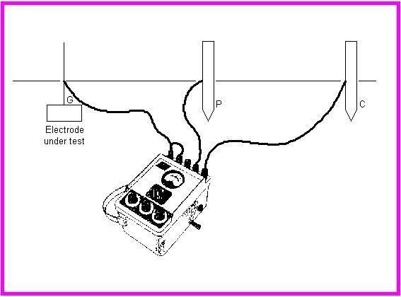
4- Set up equipment as shown in Figure 2, driving probes to a depth of 2 feet (0.6 m) minimum, into the ground.


Figure 2. Meter setup for fall-of-potential measurement


Warning: Severe shock can occur if equipment safety procedures are not followed correctly.

5- Resistance readings at potential probe spacing equal to 0.2 C, 0.4 C, and 0.6 C, are taken as shown in Figure 3.These are resistances R1, R2, and R3 respectively.


Figure 3. Probe location with resistance graph comparison


6- Calculate the slope variation coefficient using the following formula:


7- Interpret the results.


Figure 4. Table of values for PT / C related to µ


With µ calculated, and found to be   ≤ 1.59, the value of PT/C is taken from the table of values in Figure 4. If µ is not within this range, extend the current probe farther from the grid.
PT will be the distance of the potential probe position to the test grid where the true resistance should be measured.
Measure the true resistance by inserting the potential probe at the corresponding distance PT or µ (c).


Example#2:


Determine the CP probe distance from a grounded system that is 300m X 200m in area. 


Solution: 


Using the formula,


Example#3:


Repeat the same in example#2 but with a grid measuring 150m X 175m. 


Solution:


Example#4:


Resistance readings at potential probe spacing equal to 0.2 C, 0.4 C, and 0.6 C, are taken. These correspond to resistances R1, (0.4) R2, (0.8) and R3 (1.2). What is the resistance measurement and where should the PT probe be placed to obtain the true value? 


Solution:


Example#5:


Resistance readings at potential probe spacings were found to be; (0.6) (0.85) (1.12), what is the location of Pt.


Solution:


Example#6:

Calculate µ for the location and determine where the true value should be measured. Values given are (0.5) (1.1) and (2.05). 


Solution: 


Practice#1B: How to Estimate Minimum Ground Grid Resistance


Follow the steps in this Practice to calculate the Minimum grid resistance as follows:

Calculate the Minimum ground resistance of the grid using the following formula:


Where:

Rg  = ground resistance in Ω
  ρ  = average earth resistivity in Ω/m
  A  = area occupied by the ground grid in m2
  π  = 3.14


Example#7:


Calculate the Minimum ground resistance of a Transformer Yard grid 100 x 70 meter, knowing that ρ = 750 Ω/m.


Solution: 


Using the formula: 


Example#8:


Calculate the Minimum ground resistance (Rg) of the grid if soil resistivity is 2000 Ω/m for a ground grid 100 x 60 meter.


Solution: 


A = 100 m x 60 m = 6000 square meters

Using the following formula: 


Practice#1C: How to Estimate Upper Limit of Ground Resistance


Follow the steps in this Practice to calculate Upper Limit of Ground Resistance as follows:

Calculate the Upper Limit of Ground Resistance of the grid using the following formula:


Where:

Rg = station ground resistance in Ω
Ρ = average earth (soil) resistivity in Ω/m
A = the area occupied by the ground grid in m2
L = the total buried length of conductors in m
Π = 3.14


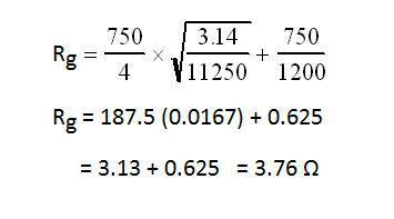
Example#9:


Calculate the Upper Limit of ground resistance (Rg) of the grid if soil resistivity is 750 Ω/m for a ground grid shown in below figure. 


Solution:

A = 11250 m2

L = 1200 m

To solve for Rg use the formula and plug in the above figures.


Example#10:


Calculate the Upper Limit of ground resistance (Rg) of the grid if soil resistivity is 180 Ω/m for a ground grid shown in below figure.


Solution:


L (Total length grounding grid conductors) = (4 x 200) + (6 x 150) + (6 x 50) = 2000 meters

A = 200 x 150 = 30,000

Plugging in the numbers for the formula:


In the next article, I will explain Other Practices for Inspection of ground Grids, Rods, and Fence grounds. Please, keep following.