In Article " Identifying Grounding Connectors and Bushings ", I explained the two methods for making the grounding connections, which were:
- Soldered Splice,
- Solderless Splice (Compression Connectors).
Today, I will explain Practice#1: How to Determine Ground Resistance as follows.
You can review the following Articles For more information:
- Verifying Ground Rod Installation
- Verifying Ground Connection and Fence Ground Installation
- Identifying Correct Grounding Tools and Equipment
|
Practice#1: How To Determine
Ground Resistance
|
|
Practice#1A: How
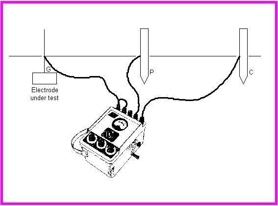
To Measure Ground Resistance
|
Example#2:
Determine the CP probe distance from a grounded system that is 300m X 200m in area.
Solution:
Using the formula,

Example#3:
Repeat the same in example#2 but with a grid measuring 150m X 175m.
Solution:

Example#4:
Resistance readings at potential probe spacing equal to 0.2 C, 0.4 C, and 0.6 C, are taken. These correspond to resistances R1, (0.4) R2, (0.8) and R3 (1.2). What is the resistance measurement and where should the PT probe be placed to obtain the true value?
Solution:

Example#5:
Resistance readings at potential probe spacings were found to be; (0.6) (0.85) (1.12), what is the location of Pt.
Solution:

Example#6:
Calculate µ for the location and determine where the true value should be measured. Values given are (0.5) (1.1) and (2.05).
Solution:
|
Practice#1B: How to
Estimate Minimum Ground Grid Resistance
|
|
Follow the
steps in this Practice to calculate the Minimum grid resistance as follows:
Calculate the Minimum ground
resistance of the grid using the following formula:
Where:
Rg =
ground resistance in Ω
ρ = average earth resistivity
in Ω/m
A =
area occupied by the ground grid in m2
π =
3.14
|
Example#7:
Calculate the Minimum ground resistance of a Transformer Yard grid 100 x 70 meter, knowing that ρ = 750 Ω/m.
Solution:
Using the formula:
Example#8:
Calculate the Minimum ground resistance (Rg) of the grid if soil resistivity is 2000 Ω/m for a ground grid 100 x 60 meter.
Solution:
A = 100 m x 60 m = 6000 square meters
Using the following formula:
|
Practice#1C: How
to Estimate Upper Limit of Ground Resistance
|
|
Follow the steps
in this Practice to calculate Upper Limit of Ground Resistance as follows:
Calculate the Upper Limit of
Ground Resistance of the grid using the following formula:
Where:
Rg = station
ground resistance in Ω
Ρ = average earth (soil)
resistivity in Ω/m
A = the area occupied by the
ground grid in m2
L = the total buried length of
conductors in m
Π = 3.14
|
Example#9:
Calculate the Upper Limit of ground resistance (Rg) of the grid if soil resistivity is 750 Ω/m for a ground grid shown in below figure.
Solution:
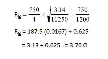
A = 11250 m2
L = 1200 m
To solve for Rg use the formula and plug in the above figures.

Example#10:
Calculate the Upper Limit of ground resistance (Rg) of the grid if soil resistivity is 180 Ω/m for a ground grid shown in below figure.

Solution:
L (Total length grounding grid conductors) = (4 x 200) + (6 x 150) + (6 x 50) = 2000 meters
A = 200 x 150 = 30,000
Plugging in the numbers for the formula:

In the next article, I will explain Other Practices for Inspection of ground Grids, Rods, and Fence grounds. Please, keep following.


(4 x 200) + (6 x 150) + (6 x 50) plz explain this why 4 and 6 multiplier?
ReplyDelete